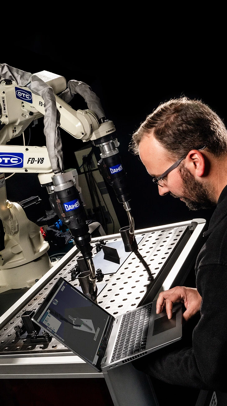
Add more functions to your robot configuration
OUR OTC DAIHEN SOFTWARE SOLUTIONS
Our broad software tool portfolio addresses all different needs to the user:
Extensions of the system software for easy integration and expansion of automation cells, solution adapted software for handling and welding applications, as well as monitoring and sensor software to visualize productivity.

System Software:
- Robot Language
- Synchronized Motion Control
- Multi Unit Control
- External Axis Shift Function
- Endless Rotation
- Pitch Copy & Shift
- Input shift function
- Cross Mastering
Welding Software:
- TIG Pulse Welding
- Robot RS Control
- Weaving Function
- Multi Pass Welding
- Synchro TIG
- Synchro MIG & FC MIG
- Stitch Pulse Welding
Handling Software:
- Fine Motion
- Palletize
- Force Sensor
Monitoring Software:
- Oscilloscope Function
- Visual Maintenance Support
Synchromotion
Synchromotion is a motion control method that allows the operator to move more than one mechanism synchronously to keep the relative torch orientation and welding speed constant in the welding seam - for synchronized welding with auxiliary axes. Multi Synchromotion refers to the dynamic switching of auxiliary axes in and out of synchromotion operation. This function is used when several positioners are arranged around a manipulator and Synchromotion operation can be switched from one positioner to another.
Multi unit control
The Multi unit control function divides all mechanisms connected to a control unit into a number of groups called "units". It controls the robot on the basis of the individual units. The units are preset according to the customer's specifications before shipment from the factory or before delivery.
Multi drive
The Multi drive function makes it possible to control several traverse or rotary axes, each of which has the same specification as a single mechanism.
This control method is particularly suitable for moving a manipulator or a component on long traverse mechanisms (multi-axis gantries) or for welding long components in horizontal positioners.
Endless rotation
When a positioner is rotated by one rotation, it returns to the initial position. However, since the amount of the rotation is stored, there is a difference between the position data before and after the rotation. Therefore, in continuous automatic mode, the positioner must be rotated in the opposite direction each time the program is started in order to return to the home position in terms of position data.
With the Endless rotation function, a positioner can rotate in the shortest direction to reach a desired position. This can significantly reduce cycle times.
However, it is important to note that if media are used on the positioner (e.g. air, forming gas, control lines, bus lines), the feedthroughs used must be suitable for endless rotation. It may therefore be necessary to retrofit the feedthroughs.
Palletizing
Palletizing is the stacking of workpieces according to a deposit pattern.
By programming a loading (or unloading) operation for one workpiece and by specifying the number of workpieces and the way they are to be deposited (or picked up), it is possible to determine the loading (or unloading) operations for all workpieces and to create the corresponding programs automatically.
The robot controller offers two methods for programming palletizing: The easy-to-learn "simple palletizing" method and the "complex palletizing" method, which can be applied to complex and diverse patterns.
Adaptive motion
If an offset or positional difference occurs between the robot and the pickup tool, or when handling or mounting components, a collision occurs between the part to be mounted and the part to which it is to be mounted.
A floating mechanism is required to prevent this collision.
The adaptive motion function makes it possible to simulate this floating mechanism and thus prevent the collision. This eliminates the need for a mechanical solution.
The adaptive motion function can be used for the following applications:
- Insertion (e.g. bolt in hole)
With normal programming, the insertion position and the insertion direction must be programmed with very high precision so that the part to be inserted does not jam.
With the adaptive motion function, programming can be done with less precision, as slight deviations can be compensated. - Removal of parts from a machine
The adaptive motion function allows the robot to remove components from a machine while following the movements of the machine. - Positioning by touch
The adaptive motion function enables the robot to position the component in a tool by touching it.
External axis shift
If auxiliary axes, i.e. trolleys, positioners or servo clamps with robot-controlled motors, are connected in a system, they can be shifted in a program. This function is called external axis shift. Depending on the system configuration, this shift can be executed simultaneously or synchronously. This function can shift already created programs. The shifted program can be executed, saved or saved under a new name.
It is also possible to shift certain program steps in a program.
External shift
The external shift function shifts positions that have been stored in the work program by specified values that are communicated to the controller from outside. The shift takes place in real time. The shift is performed in automatic mode and is only temporary, i.e. without overwriting the positions stored in the working program.
In order for the displacement to be executed, the corresponding values, lengths and angles must be communicated to the control.
In some cases the displacement values are determined by optical sensors and other external devices, in others the displacement values are already available as a precalculation.
Pitch copy and shift
The Pitch Copy and Shift functions enable the transfer of a reference program for machining several identical workpieces that are at the same distance from each other.
Transferred to positioners and trolleys, this is a helpful function if many workpieces of the same size are to be machined at the same intervals, since the actual part program only has to be written once.
Synchro-MIG welding
Synchro-MIG welding is a welding process in which the welding parameters can be switched synchronously with the reaching of an end point of a pendulum movement. It is particularly efficient when welding sheets of different thicknesses, since, for example, welding can be performed on the thick sheet with a high amperage and on thin sheets with a low amperage.
FC-MIG welding
FC-MIG welding is a welding process in which the welding parameters are switched between two parameters with a certain frequency.
Stitch pulse welding
Stitch pulse welding (=stitch pulse welding) is a welding process that produces a stitching path in which the stitching points are shingled and is suitable for welding thin sheets, since the heat influence on the base material is minimized.
The following three operations are repeated in this process:
- Starting and holding the arc for the specified time with the torch stopped.
- Cooling the weld with shielding gas for the specified time with the torch stopped.
- Offsetting the torch by the specified distance.
Cycle pulse welding
Cycle pulse welding is a welding process that produces a tack line where the tacking is shingled and is suitable for welding thin sheets as the heat influence on the base material is minimized. The average welding speed is higher than in tack pulse welding (=stitch pulse welding).
The following two operations are repeated in this process:
- Pulse output period
Performing pulse welding for the specified time while the torch is at rest. - DC output period
Moving around the specified travel distance with the arc burning.
The usual pulse welding is not performed during the movement, resulting in no weld.
Synchro-TIG welding
Synchro-TIG welding is a TIG welding process in which the wire feed pulse is synchronized in time with the welding current pulse. The following "Synchro-TIG" processes are available:
- DC Synchro-TIG
- AC Synchro-TIG
- AC-DC Synchro-TIG
TIG pulse welding
TIG pulse welding (=TIG pulse welding) means a weld produced by issuing commands in pulse form to the TIG welding power source.
In this welding method, the welding current and wire feed are pulse controlled to produce a perfect high quality weld.
All parameters required for TIG pulse welding including pulse waveform, frequency and welding parameters can be set using the weld start/end command (AS/AE).
These commands are also used to set the preheat and ramp parameters to stabilize the weld start and to prevent end craters.
RS control
The RS control function makes it possible to use an arc start signal to briefly retract the wire at the moment of arc generation.
Using the RS control function has the following effects.
- Spatter generation during arc start is reduced.
- The safety during arc ignition is increased. (An effect that is particularly positive when processing soft aluminum).
- The time required to establish a stable arc is reduced. (The start-up time is reduced to 1/3).
An AC servo torch from OTC DAIHEN is required to use the function.
Robot-RS control
The Robot-RS control function allows an arc start signal to first bring the wire into contact with the workpiece. At the moment of ignition, the torch is then retracted by the robot in the direction of the wire. A standard torch can be used for this purpose; it is not necessary to use a servo torch.
The use of the Robot-RS control function has the following effects:
- Spatter development at arc start is reduced.
- The Robot-RS function can be switched on or off with each welding start. The parameters can also be adjusted in each case.
Multi pass welding
The welding process in which a groove of a workpiece made of thick plates is welded several times in order to be filled with filler material is called multi pass welding. To perform multi-pass welding, it takes a lot of time to program all the necessary layers in a welding section individually.
With the multi-pass welding function, you can specify a section that you want to weld repeatedly. This results in a multi-pass weld with a much shorter programming time compared to methods where all passes must be programmed individually.
Welding Recorder
The "Welding Recorder" is a function that makes it possible to measure and record changes in the current welding parameters (welding current, welding voltage and wire feed load) during welding only via the teach pendant without external measuring and recording equipment.
Taught weaving
This function can be used to create pendulum patterns whose individual pendulum points are adapted to the seam geometry. Any pendulum pattern can be generated.
In addition to the pendulum parameters (frequency and speed), at least two points can be programmed on the pendulum pattern (pendulum points) that are adapted to the component and the application.
Depending on the parameters and the number of pendulum points, the following pendulum types can be executed:
- Loop points
- Reverse movement between points
- Circular movement perpendicular to the direction of movement
- Circular movement perpendicular to the torch
- Pendulum movement along the welding line
Thermal spraying
The "thermal spraying" function makes it possible to apply a layer thickness uniformly with the robot. The thermal spraying types are divided into four main types according to the shape of the workpieces to be sprayed.
- Flat surfaces
- Curved surfaces
- Polyhedral surface spraying
- Rotational body spraying
The flame spraying function generates spray patterns for the main types and controls the speed using the "extended synchronous control function" and the "proportional speed control function", which is used exclusively for thermal spraying of rotating workpieces.
Oscilloscope function
The robot controller basically consists of the motion control unit that calculates and controls the position from a given work program, an input/output unit that manages the input/output signals and a driver unit that controls the servo motors.
The oscilloscope function makes it possible to measure motion data such as speed, position, acceleration commands, speed commands to the servo motors, servo data such as control currents, and the states of the I/O signals without an additional device using only the teach pendant.
The operation and use of the oscilloscope function requires a minimum of technical knowledge. The function is only recommended for users who are confident with the robot controller and familiar with the basic operation of a real oscilloscope.
Interface Panel
By arranging the pushbuttons, lamps, etc. on the touch panel of the teach pendant, the interface control panel function supports the connection with the line control and the control of the peripheral devices. The arrangement of the operating switches, indicator lamps, etc., which used to be realized by hardware circuits, can be realized with this function on the touch panel of the teach pendant.
Force Sensor
The force control function (Force Sensor) enables the use of force/torque data determined by a force sensor via a special interface.
By using this interface, it is possible to select the robot motion based on the force that occurs and output signals corresponding to the force that occurs to an external device. By using the force control, it is also possible to push the workpiece with a constant force and touch the workpiece under the specified conditions.
Auto Calibration
The automatic calibration function can be used to compensate for shifts in torch orientation caused by changes in the installation position or the basic position of the robot axes.
Shifts in torch orientation can be caused by collisions or by the replacement of motors and gears.
The main task of the auto-calibration function is fully automatic displacement detection and compensation.
With this function and the required calibration sensor, functions such as cyclical torch measurement and the occasional check of the robot base position can be performed fully automatically.